
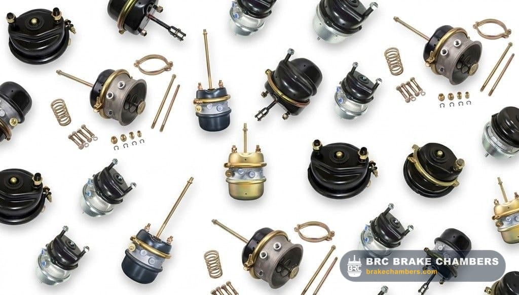
Brake Chamber Visual Identification Guide - Size, Stroke & Type
Identify brake chamber size, stroke type, and manufacturer without a part number. Field-tested methods for technicians working on rusted, corroded, or unmarked chambers in severe-duty environments.
Why Brake Chamber Visual Identification Matters
In severe-duty environments - winter road salts, high moisture, and constant debris exposure - part number tags and embossed markings can rust away or become illegible within months. Technicians must rely on visual and dimensional characteristics to identify the size and stroke type of a chamber for a safe, identical replacement. Guessing the size is a serious liability and a DOT, CVSA, or equivalent regional violation.
Identifying Brake Chamber Size by Clamp Band Diameter
The most reliable way to identify a service brake chamber size without a tag is to measure the outside diameter (OD) directly across the center of the clamp band. All BRC chambers conform to these standard dimensions.
- Type 20 - OD: 6.8 in (173 mm)
- Type 24 - OD: 7.1 in (180 mm)
- Type 30 - OD: 8.2 in (208 mm)
- Type 36 - OD: 9.0 in (229 mm)
Identifying Long-Stroke (LS) Brake Chambers
Long-stroke chambers provide critical extra braking margin. Mixing standard-stroke and long-stroke chambers on the same axle is a serious safety violation and illegal in most commercial vehicle jurisdictions. Because of this, manufacturers include specific visual indicators so inspectors and technicians can identify chamber type from underneath the vehicle in poor lighting.
- Square Ports: The pneumatic air ports on the center section are cast into a raised, square or rectangular boss. Standard-stroke ports are flush or round.
- Trapezoidal ID Tag: The metal identification tag secured under the clamp band bolt is trapezoidal. Standard-stroke tags are round or rectangular.
- Deep Stamping on Rear Housing: The rear housing typically features a deep, permanent stamped marking stating "LONG STROKE" or "LS".
Measure the Pushrod Length
The pushrod length is measured from the base of the chamber body (where it mounts to the bracket) to the very center of the clevis pin hole.
- Ensure the chamber is fully released (caged or no air pressure).
- Do not measure just the exposed rod; measure from the mounting face.
Determine Port Angles
Air ports are clocked relative to the mounting studs. Looking directly at the rear of the chamber with the mounting studs at 3 o'clock and 9 o'clock, determine the degree angle of the ports.
- Standard port configurations are typically 0°, 45°, 90°, or 180°.
- Match this angle to ensure your air hoses can reach without kinking.
Brake Chamber Identification FAQs
Common questions from technicians identifying unmarked brake chambers in the field.